Another Great Tech Tip To Help You Upgrade Your Hoof Or Pierce Belt Drive Governor – Tech Tip #136
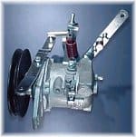
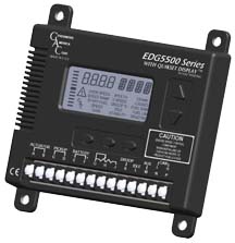
In our Tech Tip #80, Governors on Industrial Engines: A Brief Overview, we discussed the three main styles of governors. Since then there have been significant changes in the industry. Both Hoof Products and the Pierce Company are now no longer offering governors. As a result, we are helping people upgrade to electronic governors made by Governors America Corp into existing as well as new applications.
We even have developed kits to help people retrofit an electronic governor to Ford CSG649 Industrial Engines that have a failed Hoof/Pierce BD540 belt drive governor in a wood chipper. We also have kits to retrofit an electronic governor to a Ford LSG875 engine in Onan generators running a failed Hoof/Pierce BD916 belt drive governor and governors for other engines such as the Ford LSG423 and the Ford LRG425.

Our kits are complete and come with an actuator, controller, and a magnetic sensor or pick-up device to measure engine speed. This Tech Tip, one of a series we publish for the engine industry, shows how to install this speed sensor.
The first step is to locate the mag pickup correctly over the flywheel ring gear which is inside the flywheel housing. This may require you to remove the PTO or hydraulic pump adaptor from the back of the engine to gain access to the flywheel and flywheel ring gear using a machinist’s ruler with a slide stop, insert the ruler into the bell housing as far as to where it touches the ring gear. Push the slide stop down to where the ruler is at the back edge of the flywheel housing transfer this measurement, e.g., the distance from the end of the bell housing to the ring gear, to the top of the bell housing, adjusting as necessary if the top of the bell housing is curved.

Be aware that the center of the ring gear will be an additional .25″ further in than the distance you just measured with your ruler.
To avoid electrical interference install the magnetic pickup on the opposite side of the bell housing from the starter motor.
Using a center punch, mark a hole in the flywheel or bell housing directly above the ring gear. Drill and tap this hole. Note: after drilling and tapping this hole and while the PTO is removed from the engine, use compressed air to blow out any filings you just created from the ring gear area.
To check if the ring gear is out of round or has stripped teeth, insert a used bolt into this hole and screw in to where it touches the ring gear. Withdraw the bolt .010.

Rotate the engine to determine if the ring gear at any point touches the bolt. Withdraw this bolt.
Screw in the magnetic pick up and leave an air gap between .04 and .12″ and you are done. You’ve just installed your first magnetic pickup and your new electronic governor will soon be operational!
We hope that you will find this Tech Tip helpful. We believe that Tech Support matters and welcome your comments or suggestions. Please email our Dr. Diesel™ at DrDiesel@FoleyEngines.com or call him at 800.233.6539 with your thoughts.

 In our Tech Tip #40, Governors on Industrial Engines: A Brief Overview, we discussed the three main styles of governors. Since then there have been significant changes in the industry. Both Hoof Products and the Pierce Company are now no longer offering governors. As a result, we are helping people upgrade to electronic governors made by Governors America Corp into existing as well as new applications.


